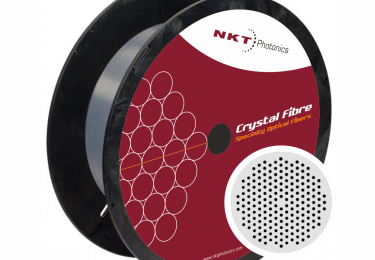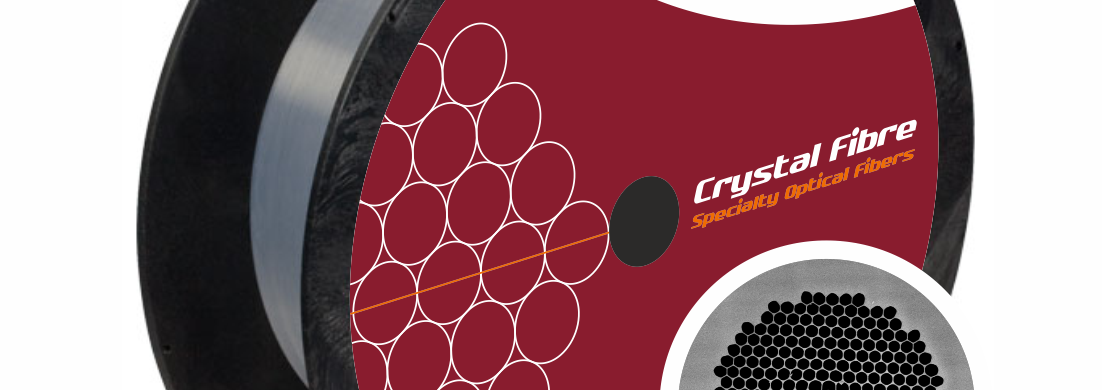
Hollow core photonic crystal fibers
Hollow-core photonic bandgap fibers turn conventional fiber technology inside out by guiding the light in a hollow-core. This unique waveguide is ideal for sensing, imaging, and ultrashort pulse applications.
Our hollow-core photonic bandgap fibers deliver ultrashort pulses without non-linear effects or material damage and tolerate tight bending without impact on transmission. Hollow-core fibers are radiation insensitive and suitable for harsh radiation environments.

Key Features
> 98% of the optical power in the core
Can be gas or particle-filled
Ultra-low bend loss
Low Fresnel reflections at end faces
Group index close to unity
Radiation insensitive


For a large variety of applications
More than 98% of the mode is confined in air, which makes the fibers very radiation insensitive and suitable for radiation hard environments.
In hollow-core photonic bandgap fibers, a microstructured silica cladding with air holes confines the light inside a hollow core. They enable a large variety of applications that require performances that can not be met using traditional solid-core fibers.
Hollow-core fibers are ideal for narrow linewidth delivery, power delivery, pulse shaping and compression, nonlinear optics, gas spectroscopy, fiber optic gyroscopes, and sensors.
Unique properties
The hollow core allows control of the gas composition and pressure, enabling extremely long interaction lengths between the light and the gas.
The weak interaction between the fundamental mode and the surrounding silica also makes these fibers radiation insensitive.
Reduced non-linearities
Since only a small fraction of the light propagates in silica, the effect of material non-linearities is significantly reduced compared to solid core fibers.
Our standard products cover five wavelength ranges around the wavelengths 800 nm, 920 nm, 1060 nm, 1300 nm, and 1550 nm. Get in touch to discuss custom wavelengths.
Want more details?
If you want more details about how to handle optical fibers: Strip, cleave, and couple them, we have some application notes for you.
Optical fibers require proper handling to ensure a long lifetime and prevent fiber breaking. Read this guideline to learn how to handle optical fiber to keep both fiber and operator safe.
Read this application note if you would like to learn how to handle our optical fibers, e.g., including how to strip the protective coating, how to cleave the fibers, and how to couple light to and from the fibers.
Learn about optical damage of fiber facets in pulsed laser systems and how these depend on the pulse length.
Specifications
1) Full 1/e2 width of the near field intensity distribution.
(single-layer acrylate)